


*Architecture=System floor plan (limited)
On June 10, 2016, Nintendo Co., Ltd. filed in the US via the United States Patent and Trademark Office several patent applications related to Nintendo Switch. They were published today December 15, 2016. The applications are:
Appl. No. 15/178972, GAME CONTROLLER
Appl. No. 15/178991, GAME CONTROLLER
Appl. No. 15/179011, GAME CONTROLLER
Appl. No. 15/178984, SUPPORTING DEVICE, CHARGING DEVICE AND CONTROLLER SYSTEM
Appl. No. 15/179022, INFORMATION PROCESSING SYSTEM, INFORMATION PROCESSING DEVICE, CONTROLLER DEVICE AND ACCESSORY
The applications are quite similar in content. Therefore I have chosen to focus on the one called Supporting Device, Charging Device and Controller System. It gives good information on how the controller functions and also provides information on system architecture. It is quite lengthy and the drawings amount is 63. Due to character limitation, I will select parts I deem more interesting of the application.
Inventors: IWAO; Toshiaki; (Kyoto, JP) ; TAKEI; Masaya; (Kyoto, JP) ; FUJITA; Kumpei; (Kyoto, JP) ; IKUTA; Hiroki; (Kyoto, JP) ; HIROSE; Shinji; (Kyoto, JP) ; AKAMA; Tetsuya; (Kyoto, JP) ; TSUCHIYA; Hitoshi; (Kyoto, JP)
Applicant: NINTENDO CO., LTD.
Kyoto
JP
Family ID: 1000002022311
Appl. No.: 15/178984
Filed: June 10, 2016
Abstract
An example supporting device supports two game controllers. The supporting device includes a support section and a main section connected to the support section. The support section includes a first slide member and a second slide member. The first slide member is provided in an area of the support section toward a first side in a predetermined direction, and the second slide member is provided in an area toward a second side. The slide members are capable of slidably engaging with rail members of the respective game controllers in a predetermined slide direction. The first slide member includes a first terminal provided on a first opposing surface. The second slide member includes a second terminal provided on a second opposing surface. The main section includes a first grip portion for being gripped by a user, and a second grip portion for being gripped by the user.
Claims
1. A game controller supporting device for supporting a first game controller and a second game controller, wherein: the first game controller includes a first rail member configured for allowing the first game controller to be attached to the supporting device; the second game controller includes a second rail member configured for allowing the second game controller to be attached to the supporting device; the supporting device includes: a support section; and a main section connected to the support section; the support section includes: a first slide member in an area of the support section toward a first side in a predetermined direction, the first slide member being configured to slidably engage with the first rail member of the first game controller in a first slide direction; and a second slide member in an area of the support section toward a second side in the predetermined direction, the second slide member being configured to slidably engage with the second rail member of the second game controller in a second slide direction; the first slide member includes: a first groove having a bottom surface formed along the first slide direction; a first facing surface, wherein the first slide member has a first side and a second side in the first slide direction, and the first facing surface is in an end portion on the first side of the first slide member so as to face a portion of the bottom surface of the first groove; and a first terminal on the first facing surface, which first terminal is configured to be electrically connected to the first game controller; the second slide member includes: a second groove having a bottom surface formed along the second slide direction; a second facing surface, wherein the second slide member has a first side and a second side in the second slide direction, and the second facing surface is in an end portion on the first side of the second slide member so as to face a portion of the bottom surface of the second groove; and a second terminal on the second facing surface, which second terminal is configured to be electrically connected to the second game controller; the main section includes: a first grip portion on a first side of the main section in the predetermined direction configured for being gripped by a user; and a second grip portion on a second side of the main section in the predetermined direction configured for being gripped by the user; the support section includes: a connector; a power supply configured to supply power, via the connector, to the first game controller via the first terminal, and to the second game controller via the second terminal; and a light-emitter configured for emitting light indicating that the power supply is supplying power to at least one of the first game controller and the second game controller; the first game controller includes a first stop member, wherein the first stop member is configured so that when the first rail member has been inserted up to a predetermined first position into the first slide member, the first stop member resists a slide movement, in an opposite direction, of the first rail member against the first slide member, the opposite direction being a direction opposite to a direction in which the first slide member is insertable into the first rail member; the first slide member includes a first stop-receiving portion, wherein the first stop member is further configured so that when the first rail member of the first game controller has been inserted up to the first position into the first slide member, the first stop member engages with the first stop-receiving portion; the second game controller includes a second stop member, wherein the second stop member is configured so that when the second rail member has been inserted up to a predetermined second position into the second slide member, the second stop member resists a slide movement, in an opposite direction, of the second rail member against the second slide member, the opposite direction being a direction opposite to a direction in which the second slide member is insertable into the first rail member; and the second slide member includes a second stop-receiving portion, wherein the second stop member is further configured so that when the second rail member of the second game controller has been inserted up to the second position into the second slide member, the second stop member engages with the second stop-receiving portion.
BACKGROUND AND SUMMARY
[0003] There are conventional controllers capable of accommodating an information processing device therein. For example, there is a controller capable of accommodating a mobile telephone by means of a left key plate and a right key plate. Specifically, the controller includes a spring for sliding one key plate toward the other key plate so that the mobile telephone is sandwiched between the left and right key plates, thereby accommodating the mobile telephone.
[0004] It is only the controller that includes a holding mechanism (i.e., the key plates), but the mobile telephone does not include a holding mechanism. Therefore, the controller can easily come off the mobile telephone.
[0005] Thus, the present application discloses a supporting device with which it is possible to reduce the possibility of the supporting device coming off the information processing device.
[0006] An example supporting device described herein is a device for supporting a first game controller and a second game controller. The first game controller includes a first rail member configured for allowing the first game controller to be attached to the supporting device. The second game controller includes a second rail member configured for allowing the second game controller to be attached to the supporting device.
[0007] The supporting device includes a support section and a main section connected to the support section.
[0008] The support section includes a first slide member and a second slide member. The first slide member is in an area of the support section toward a first side in a predetermined direction, the first slide member being configured to slidably engage with the first rail member of the first game controller in a first slide direction. The second slide member is in an area of the support section toward a second side in the predetermined direction, the second slide member being configured to slidably engage with the second rail member of the second game controller in a second slide direction.
Drawings


[0074] FIG. 17 is an exploded view showing an example of a reinforcement member and an insulation sheet provided on a slider;


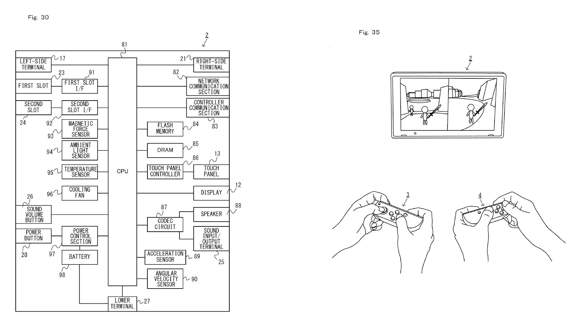
[0087] FIG. 30 is a block diagram showing an example internal configuration of the main unit;

[0088] FIG. 31 is a block diagram showing an example internal configuration of the information processing device;

[0089] FIG. 32 is a block diagram showing an example internal configuration of the cradle;


[0109] FIG. 52 is a diagram showing an example accessory to which controllers can be attached;


[0111] FIG. 54 is a six-sided view showing another non-limiting example extension grip;


[0778] FIG. 60 is a diagram showing an example HMD accessory to which the main unit 2 can be attached. An HMD accessory 230 shown in FIG. 60 includes a housing 231 and belts 232a and 232b. One end of the belt 232a is attached to one end of the housing 231, and one end of the belt 232b is attached to the other end of the housing 231. Although not shown in the figure, the other end of the belt 232a can be removably connected to the other end of the belt 232b. Thus, the housing 231 can be mounted on the head of the user by connecting together the two belts 232a and 232b around the head of the user. Note that there is no particular limitation on the mechanism for allowing the HMD accessory 230 to be mounted on the head of the user.
DETAILED DESCRIPTION OF NON-LIMITING EXAMPLE EMBODIMENTS
[0121] An information processing system, an information processing device, a controller device and an accessory according to an example of the present embodiment will now be described. In the present embodiment, the information processing system includes an information processing device 1 and a cradle 5 (see FIG. 28). The information processing device 1 of the present embodiment includes a main unit 2 and controllers 3 and 4, which can be attached to and detached from each other, and the controllers 3 and 4 can be used separately from the main unit 2 (see FIG. 2). The information processing device 1 can be used both in a mode of use in which images are displayed on the main unit 2 and in another mode of use in which images are displayed on a separate display device such as a TV. The information processing device 1 is used as a portable device (e.g., a portable game device) in the former mode, and the information processing device 1 is used as a console-type device (e.g., a console-type game device) in the latter mode.
[0395] The main unit 2 includes a CPU (Central Processing Unit) 81. The CPU 81 is an information processing section for executing various information processes to be executed on the main unit 2. The CPU 81 executes various information processes by executing an information processing program stored in a storage section that can be accessed by the CPU 81 (specifically, an internal storage medium such as a flash memory 84 or external storage media attached to the slots 23 and 24, etc.).
[0396] The main unit 2 includes, as an example internal storage medium provided in the main unit 2, the flash memory 84 and a DRAM (Dynamic Random Access Memory) 85. The flash memory 84 and the DRAM 85 are connected to the CPU 81. The flash memory 84 is a memory used primarily for storing various data (which may be programs) saved on the main unit 2. The DRAM 85 is a memory used for temporarily storing various data and instructions used in information processes.
[0397] The main unit 2 includes a first slot interface (hereinafter abbreviated as "I/F") 91. The main unit 2 also includes a second slot I/F 92. The slot I/Fs 91 and 92 are connected to the CPU 81. The first slot I/F 91 is connected to the first slot 23, and reads and writes data from and to a storage medium of the first type (e.g., an SD card) inserted in the first slot 23, in response to an instruction from the CPU 81. The second slot I/F 92 is connected to the second slot 24, and reads and writes data from and to a storage medium of the second type (e.g., a dedicated memory card) inserted in the second slot 24, in response to an instruction from the CPU 81.
Source: Search "15/178984" at http://appft.uspto.gov/netahtml/PTO/search-bool.html
Here's a snippet from a Reddit megathread about the new information, thanks again Meelow :)
System features Touch screen [T:0131] SD card slot located on the bottom of the system [F:3] Ethernet: example scenario given where dock has wired Internet connection; in console mode the system uses this connection, and in portable mode, the system can communicate wirelessly with the dock to access the wired connection [T:0560] Sleep mode for both console and portable modes [T:0562] "Share" button of some kind confirmed; referred to as a "record button" in the details for the left Joy-con; describes using it to take screenshots [T:0168] Hardware/performance Fan inside system, active in both portable mode and console mode [T:0419 + T:0556] Dock does not appear to have a fan (thanks, /u/StinkBank) [F:32] System uses CPU (and/or GPU) and fan at less than maximum in portable mode; in docked mode, it fully utilizes these. This enables outputting higher resolutions when docked [T:0556 - T:0558] Ambient light sensor for controlling brightness [F:30] System may be docked facing forwards or backwards (thanks, /u/MrMiyamoto) [T:0385] Dock has 3 USB ports (thanks, /u/MrMiyamoto) [T:0464] Controllers Right Joy-con has IR and NFC capabilities; both have rumble and gyro [F:31] Example: alternate Joy-cons with traditional dpads + sticks, or dpads + buttons [F:48 - F:49] Small digital L/R buttons accessible on the "inside" of Joy-con (where it would attach to the system), for use when held like a sideways Wiimote [F:51] [T:0180 + T:0207] Accessories Example: head-mounted display accessory (simple VR headset) [F:60] Joy-con Grip can charge attached Joy-cons (thanks, /u/Asuparagasu) [T:0672] Various controller accessories given as examples, similar to Joy-con Grip [F:52 - F:53] Gameplay Multiplayer scenario example: 4 Joy-cons can be used on one system (does not specify a limit to the number of Joy-cons or Joy-con pairs usable at once) [F:37] What the heck? Vein authentication/vitality sensor: the IR sensor could be used to authenticate users by imaging their vein pattern; can also read their pulse [T:0495] Missing/Unknown Apparently no Ethernet port on the dock, but will almost certainly support USB adapter; see wired connection scenario above Camera and microphone: not present Analog triggers: unknown Multi-touch/capacitive touch screen: unknown Stylus: unknown; not sure if this would even be part of the patent? "In other embodiments..." The implications of passages like these are not clear. They are given as examples of things that may or may not change (differences or omissions) from the patent document to the final version, or future revisions. 4G/mobile: "Note that in other embodiments, the main unit 2 may have the function of implementing communication by connecting to a mobile communication network (in other words, a mobile telephone communication network), in addition to (or instead of) the function of implementing communication by connecting to a wireless LAN." [T:0400] Camera: "Note that while the infrared image-capturing section 123 including an infrared camera is used in the present embodiment, a visible light camera (a camera using a visible light image sensor) or other image sensor may be used, instead of an infrared camera, as an image-capturing device, in other embodiments." [T:0451] System itself could charge attached Joy-cons [T:0530] System could output directly to a TV without the need for the dock [T:0542] https://www.reddit.com/r/NintendoSwitch/comments/5ii58o/nintendo_switch_patent_megathread/ |