Progress on the fighting stick:
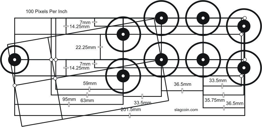
Firstly, dimensions were as follows (all are in inches):
Wood - 3/8 plywood
Top & Bottom - 10 x 15
Sides - 10 x 5.5
Front & Back - 14.25 x 5.5
Front panels - 1 x 5.5
Front door - 12.25 x 5.5
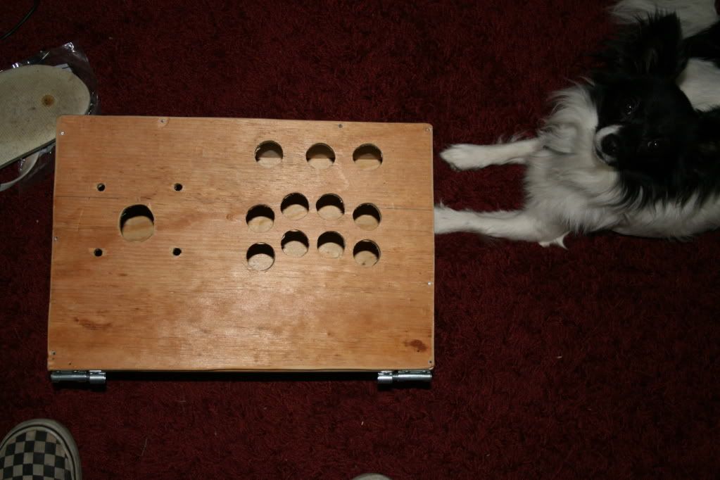
The box, from above. With Pan-pan watching.
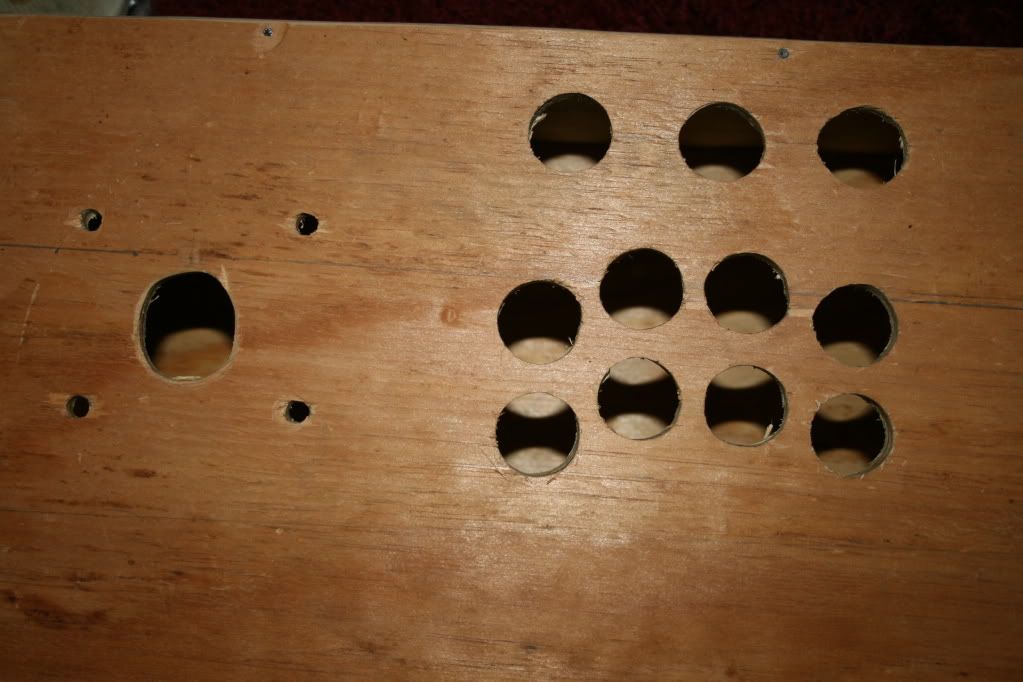
Close-up of the holes. Each button hole is about 1 inch across - just big enough to slide the buttons in. You want to be somewhere between 1 inch and 1.25 inches, and as small as possible so the buttons don't shift. Too big and the buttons will shift, and you may expose your holes as well.
The stick hole was slightly off-center so I expanded it with a rough routing bit on the drill. ANY hole you want to start smaller than necessary and expand in this fashion, if using plywood, so you don't splinter it and make a mess of yourself. This also allows you to carefully select precisely how you want the hole, so you don't accidentally do it too big.
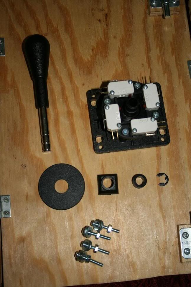
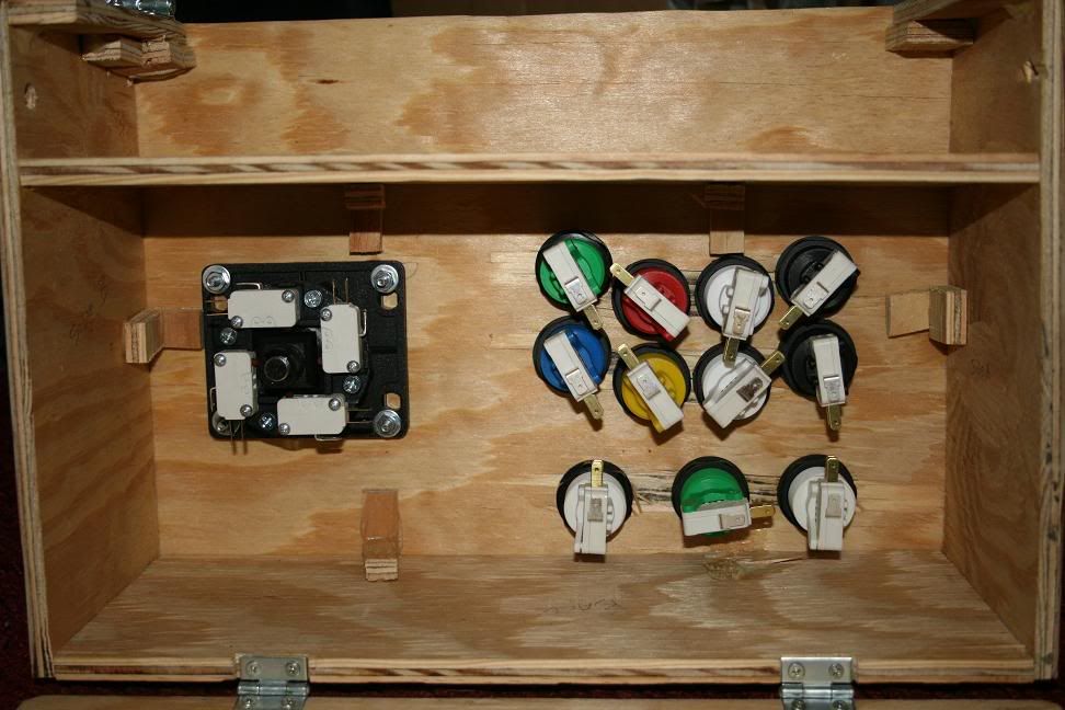
Control stick hardware.
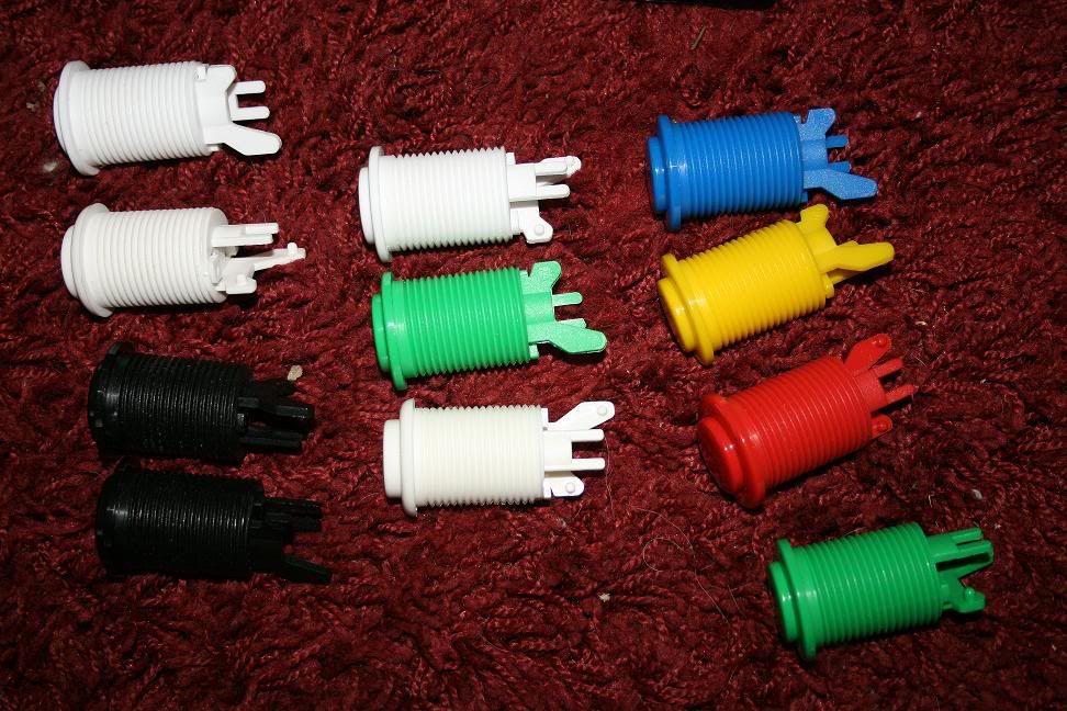
All the buttons.
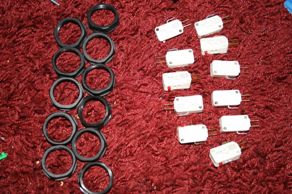
The mounting rings and microswitches for the buttons.

Now with everything in the previous pictures altogether now!
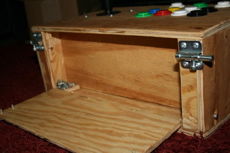
Side view, showcasing the door mechanics.
Door opened. In here, you'll find the 360 controller's battery pack, the Dreamcast controller's VMU (memory unit), and the connectors to switch between the various controllers (360, PS2, GCN, or Dreamcast). As you see, there are also two more locks.
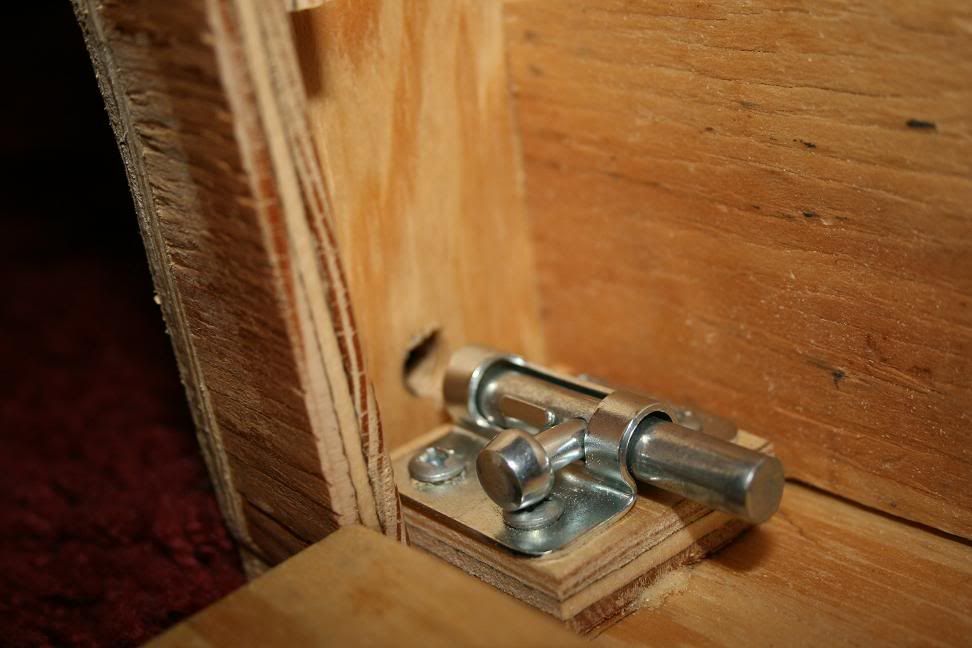
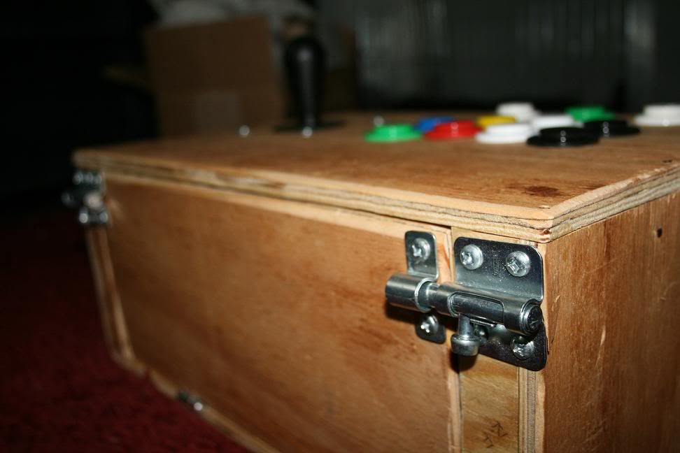
Close-up of one of the locks, showing how it works. I have it attached to a doubled layer of plywood because the screws it came with are a little longer than 1/2-inch, while the plywood is a little thinner than 3/8 inch. Had to improvise.
Anyhow, these locks work by locking into a hole on the side, effectively locking the bottom door in place.
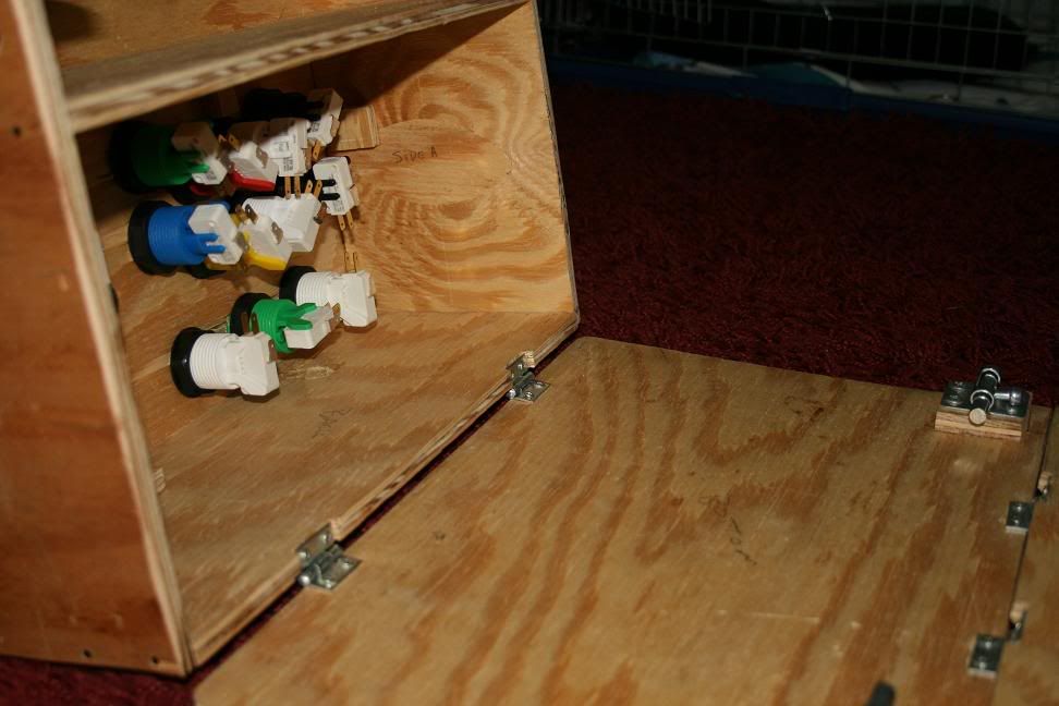
Locks in the previous image disengaged. This allows the main box door to open, revealing what
would be all the wiring and truly technical garbage on the inside. This is clearly incomplete.
Shot showing what the underside looks like with both doors opened, displaying both compartments.
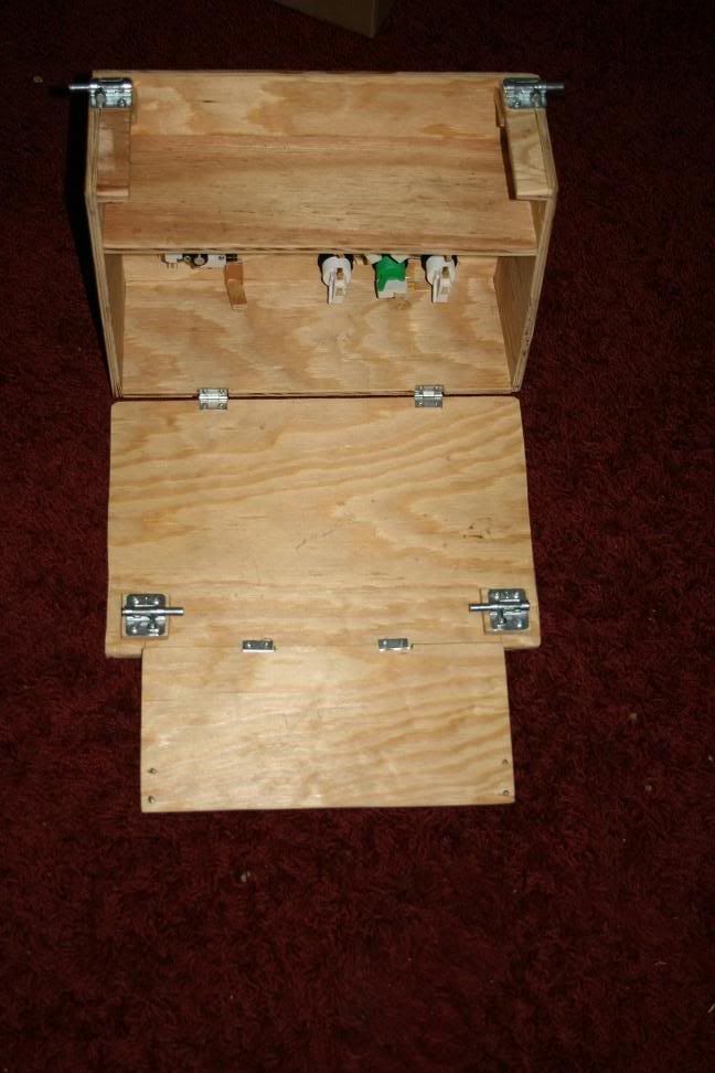
Entire thing now, open.
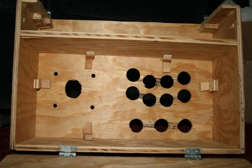
Inside, without any of the buttons or anything mounted. I was originally going to put some metal corner braces inside, but upon putting it all together, there's no space for the drill to put in the holes! I'm still debating what to do. In the meanwhile, I have the mounts for the braces - which also have screws that are too long - in place with Gorilla Glue. That's probably enough support anyways, to be honest. If I decide I want to use the braces (after all, I DID buy 'em!), then I'll drill the holes all the way through from the other side and just putty 'em up after the screws are in.
If you notice, the wood between the holes is pretty torn up. This is from not being careful enough when boring my holes. Take it slow! You'll tear up your wood if you're not careful. I lucked out and most of the damage was inconsequential.
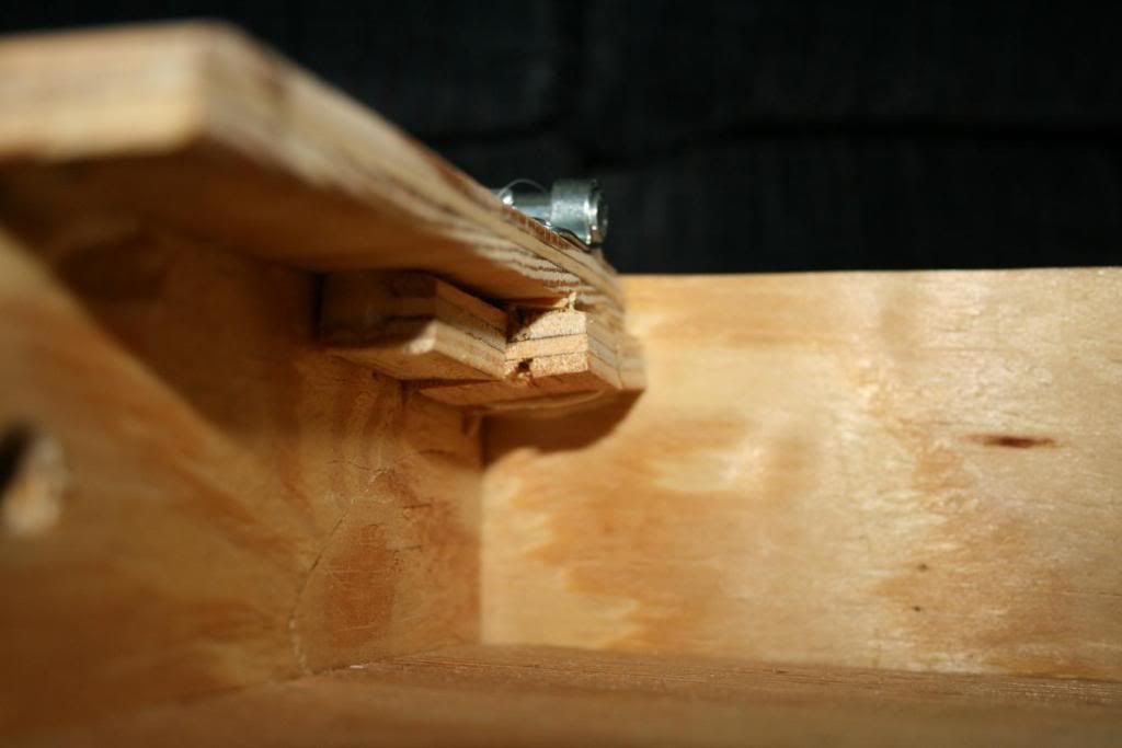
Better showing the improvisation for long screws, this for the outside locks. Just to understand why I'm doing that, look at the picture of the first door open - you'll see a large section of screw sticking through dangerously. I'm going to fix that later on.
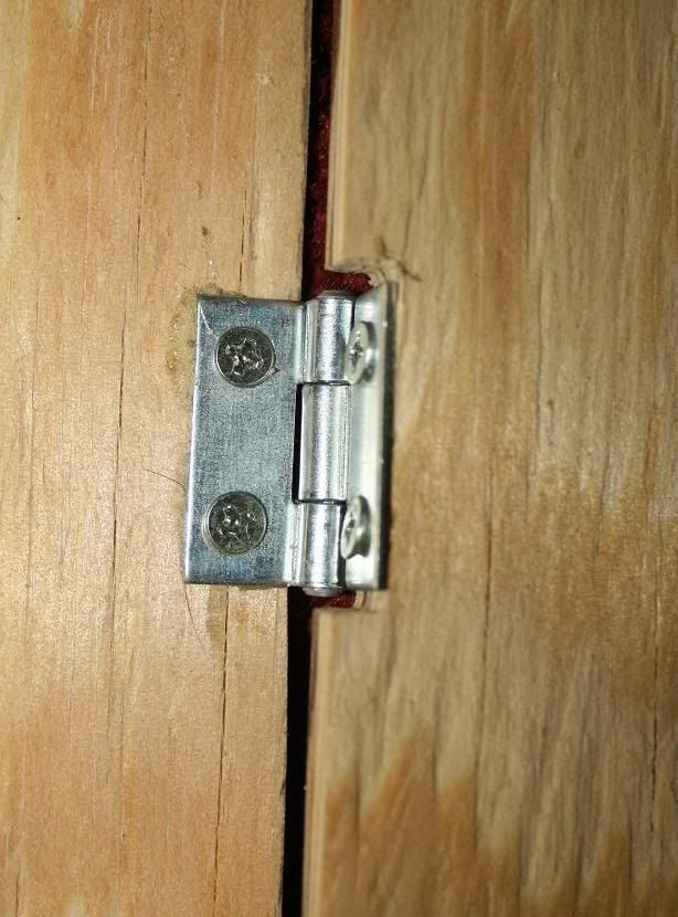
Showing my cuts for the hinges so everything can fit nice and flush.
And that's that. I'll be fixing that door screw issue, then painting it all next. Painting will consist of covering the entire thing with a sort of plaster - smoothing out any discrepancies and making it more uniform in appearance. After that, I'll sand it smooth, then paint it in two layers of black paint and at least three layers of clear protective gloss coat, possibly more. After it's painted, I'll work on the wiring and mounting of PCBs inside it. It'll be complete sometime next week, I expect.