


Originally saw this news on nintendoeverything but the article linked to a Neogaf thread and since that had a lot more info in a concise manner I figure I'd share it for you all to see below, Here's a link the original Neogaf thread.

On August 26, 2014, Nintendo Co., Ltd. filed in Japan via the JPO/INPIT a patent application titled "Information processing system, information processing program, information processing method and imaging device". It was published yesterday on April 4, 2016. The title does not say much, as often with patents, but it concerns a very peculiar device incorporating means of object detection (form and structure of an object) using cameras and mirrors, be used as a controller, a projector and more. It's one of the more technical patents I have seen from Nintendo, and it's quite lengthy, so it will likely take some time to understand. Inventor is Fumihiko Inoue:
You can read an interview with him here:
Most important here to note is that the original application is in Japanese, but JPO and INPIT also provide a machine translation (that is better than Google Translate). I'm not fluent enough in Japanese to provide a better translation, but I have read through the machine text and I consider it "understandable". Hopefully that will suffice. Hopefully it will be published in English soon via the USPTO.
Basic (excerpts)
(19) [Issuing country] Japan Patent Office (JP)
(12) [Publication Type] Patent Publication (A)
(11) [Publication number: JP 2016-45173 (P2016-45173A)
(43) [Publication date] 2016 April 4 (2016.4.4)
(54) [Title of invention] Information processing system, information processing program, information processing method and imaging device
(22) [Filing date] 2014 August 26 (2014.8.26)
(71) [The applicant]
[Identification number] 000233778
[Name] Nintendo Co., Ltd.
(72) [Inventor]
[Name] Fumihiko Inoue
[Field of the Invention] Especially this invention relates to the information processing system, the information processing program, information processing method, and imaging device which equip with a mirror the position which opposes to a camera and the camera concerned about an information processing system, an information processing program, an information processing method, and an imaging device.
[Background of the Invention] An example of a background art is disclosed in a Patent document 1. In the omnidirection three-dimensional space perception input device disclosed in this Patent document 1, the imaging means which images an omnidirection image according to the optical system which comprises a mirror part and a camera unit is provided, and the three-dimensional coordinate value in which the form and structure of an object are expressed as the stereo image of an omnidirection is extracted.
[Problem to be solved by the invention] However, the three-dimensional coordinate value which expresses the form and structure of an object in this background art as the stereo image of an omnidirection has stopped at being extracted.
At first I thought this concerned Nintendo 3DS NFC Reader/Writer considering the similar appearance. But a comparison of the two I believe shows that this is not the same, though may share some features:
12 -- Imaging device
12a -- Camera unit
12b -- Mirror part
12c -- Fixing member (fixes the camera unit)
20 -- Camera
30 -- Curved surface mirror
32 -- Fixing member (fixes the curved surface mirror)
The NFC reader/writer does not include any cameras or mirrors as far as I know.
Claims (excerpts)
[Claim 1] A camera, a mirror which opposes to the aforementioned camera and is installed -- and An information processing system comprising: The 1st part image that is equivalent to the aforementioned mirror among camera images imaged with the aforementioned camera. The 1st detection means that detects a position of an object which exists in the circumference of the camera concerned based on the 2nd part image that adjoins said 1st part image and is not equivalent to the aforementioned mirror.
[Claim 2] The information processing system according to claim 1 which detects a position of the aforementioned object based on the 1st position of the 1st object images about the aforementioned object [ in / in said 1st detection means / said 1st part image ], and the 2nd position of the 2nd object images about the aforementioned object in said 2nd part image.
[Claim 3] At least, it further has the 2nd detection means that detects the 1st positional relationship of a boundary of said 1st part image and said 2nd part image, and the 1st object images about the aforementioned object in the 1st part image concerned,
The information processing system according to claim 1 with which said 1st detection means detects a position of the aforementioned object according to said 1st positional relationship detected by said 2nd detection means.
[Claim 4] Said 2nd detection means further detects the 2nd positional relationship of the 2nd object images about the aforementioned object in a reference position of said 1st part image, and said 2nd part image,
The information processing system according to claim 3 with which said 1st detection means detects a position of the aforementioned object based on the 1st positional relationship and the 2nd positional relationship which were detected by said 2nd detection means.
[Claim 5] The information processing system according to claim 4 with which said 1st detection means detects a position of the aforementioned object based on whether said 1st positional relationship shows that said 1st object images touch the aforementioned boundary and said 2nd positional relationship.
[Claim 6] It further has the 3rd detection means that detects the 1st position of the 1st object images about the aforementioned object in the 1st part image concerned on a straight line which passes along a reference position of said 1st part image among the aforementioned camera images, and the 2nd position of the 2nd object images about the aforementioned object in said 2nd part image, The information processing system according to claim 1 with which said 1st detection means detects a position of the aforementioned object based on said 1st position detected by said 3rd detection means, and said 2nd position.
[Claim 7] The information processing system according to any one of claims 1 to 6 with which positional relationship of the aforementioned camera and the aforementioned mirror and form of the mirror concerned are determined so that light which travels in the direction parallel to the setting surface concerned may be reflected by at least one copy of the mirror concerned, when making the aforementioned mirror side install in a setting surface.
[Claim 8] The information processing system according to claim 7 with which form of relative positional relationship of the aforementioned camera and the mirror concerned and the mirror concerned is determined so that light which travels so that it may be along about the aforementioned setting surface may be reflected at the end of the aforementioned mirror.
[Claim 9] The information processing system according to claim 1 further provided with a contact judgment means which judges whether the aforementioned object contacts the aforementioned setting surface by whether said 1st object images about the aforementioned object in said 1st part image and a boundary of the 1st part image concerned and said 2nd part image contact.
[Claim 10] The information processing system according to any one of claims 1 to 9 whose field angle of the aforementioned camera is 180 degree.
[Claim 11] The information processing system according to any one of claims 1 to 10 with which the aforementioned camera can photo 360 degree of the circumference.
[Claim 18] It is an information processing program run by computer of an information processing system provided with a mirror which opposes to a camera and the aforementioned camera and is installed, The 1st part image that is equivalent to the aforementioned mirror in the aforementioned computer among camera images imaged with the aforementioned camera, An information processing program which adjoins said 1st part image and it operates as a detection means which detects a position of an object which exists in the circumference of the camera concerned based on the 2nd part image equivalent to the aforementioned mirror.
[Claim 24] a light source -- and A projector device which opposes to the aforementioned light source, is arranged and is provided with a mirror which reflects light from the aforementioned light source in the circumference.
[Claim 25] A wide angle camera which can photo 360 degree of the circumference, a mirror for cameras formed in form which opposes to the aforementioned wide angle camera, is arranged, and serves as a beam direction parallel to a predetermined surface -- and It has a light source, An electronic device by which the aforementioned light source irradiated light to at least 1 side of the aforementioned predetermined surface and the circumference.
[Claim 26] The electronic device according to claim 25 further provided with a mirror for light sources which reflects light from the aforementioned light source in at least 1 side of the aforementioned predetermined surface and the circumference.
Images
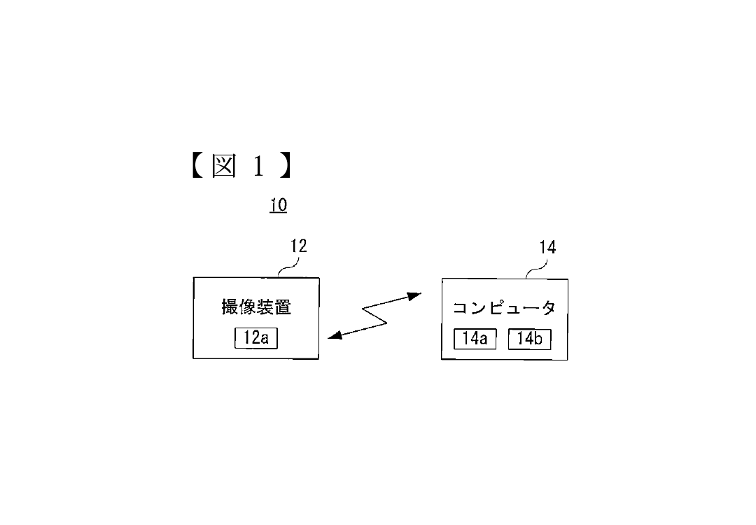
[Drawing 1]Fig.1 is an illustration figure showing the information processing system which is one working example of this invention.
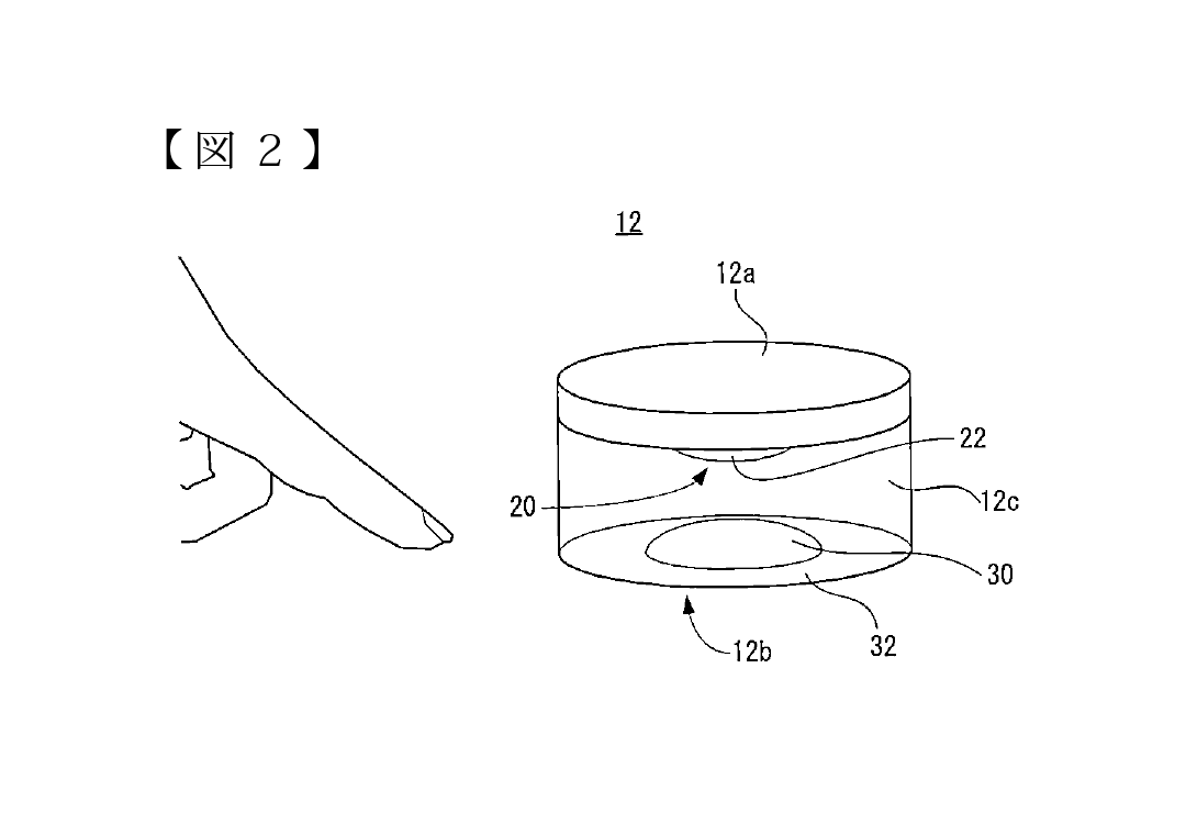
[Drawing 2]Fig.2 is an illustration figure showing an example of the appearance composition of the imaging device shown in Fig.1.

[Drawing 3]Fig.3 is a block diagram showing the electric composition of the camera unit contained in the imaging device shown in Fig.1.
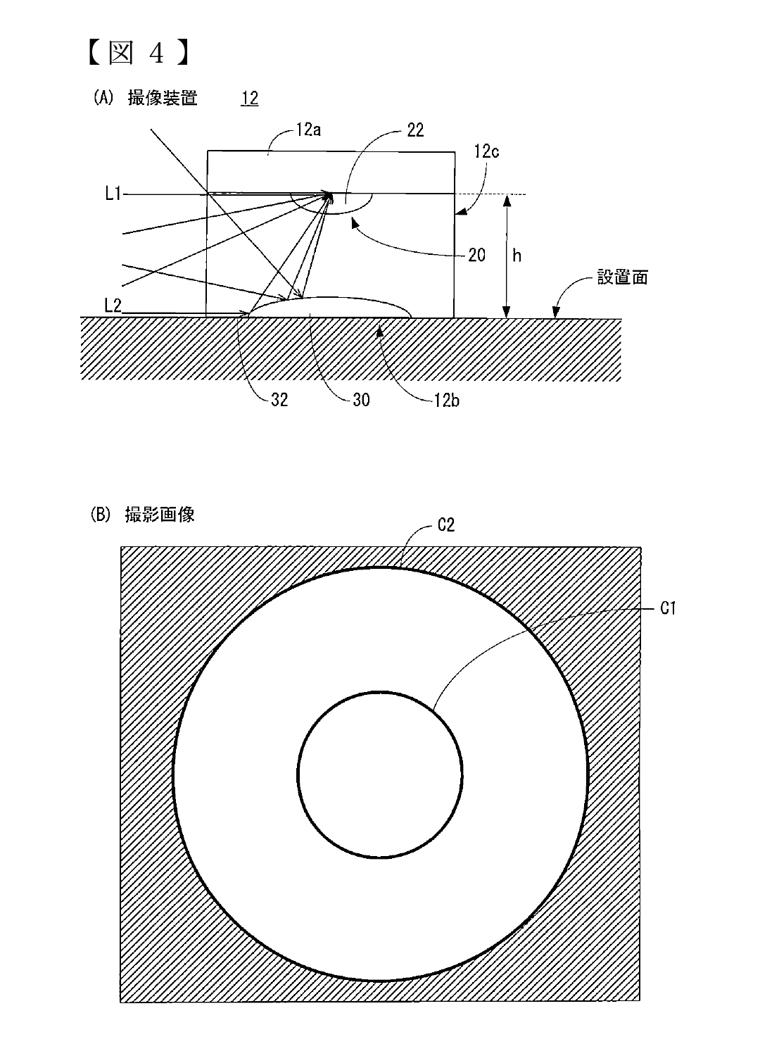
[Drawing 4]Fig.4 (A) is an illustration figure for describing the photographic range of an imaging device, and Fig.4 (B) is an illustration figure showing an example of the taken image of an imaging device.
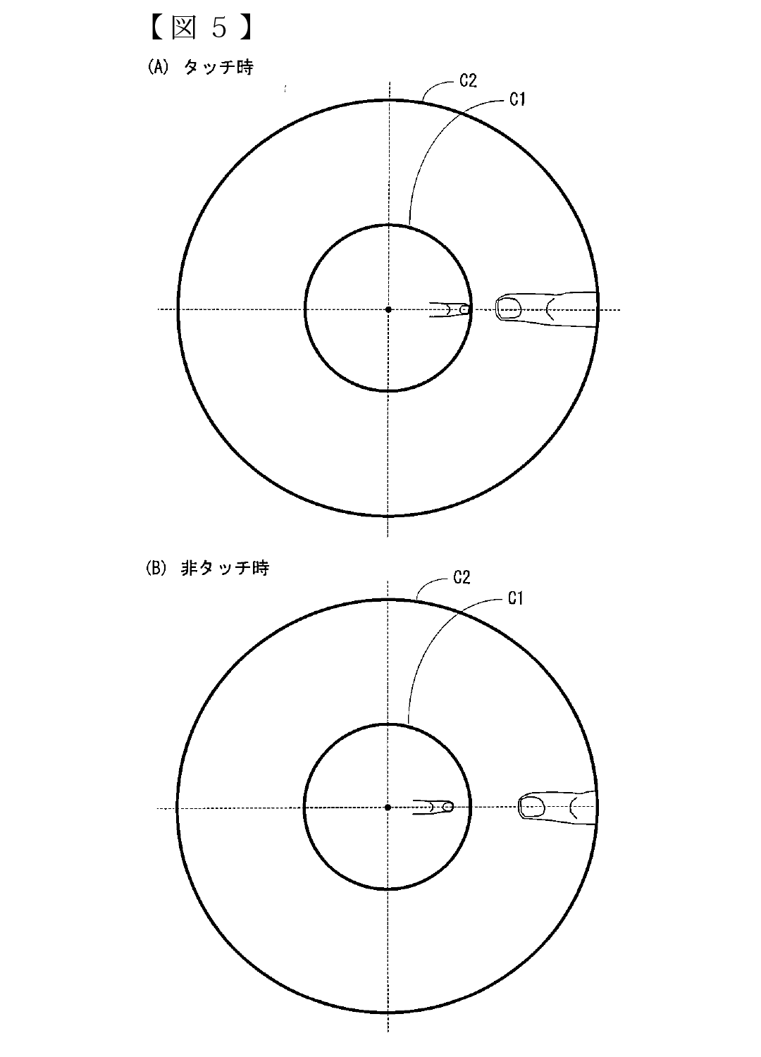
[Drawing 5]Fig.5 (A) is an illustration figure showing an example of the taken image in the case of having touched with the finger the setting surface which installed the imaging device, and Fig.5 (B) is an illustration figure showing an example of the taken image when not having touched with a finger the setting surface which installed the imaging device.
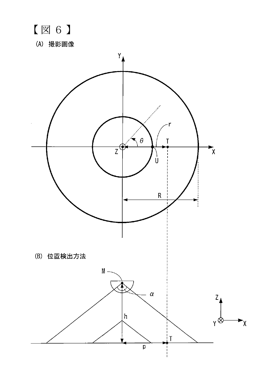
[Drawing 6]Fig.6 (A) is other examples of the taken image of an imaging device, and Fig.6 (B) is an explanatory view for describing the method of computing the position of the finger in the case of having touched.
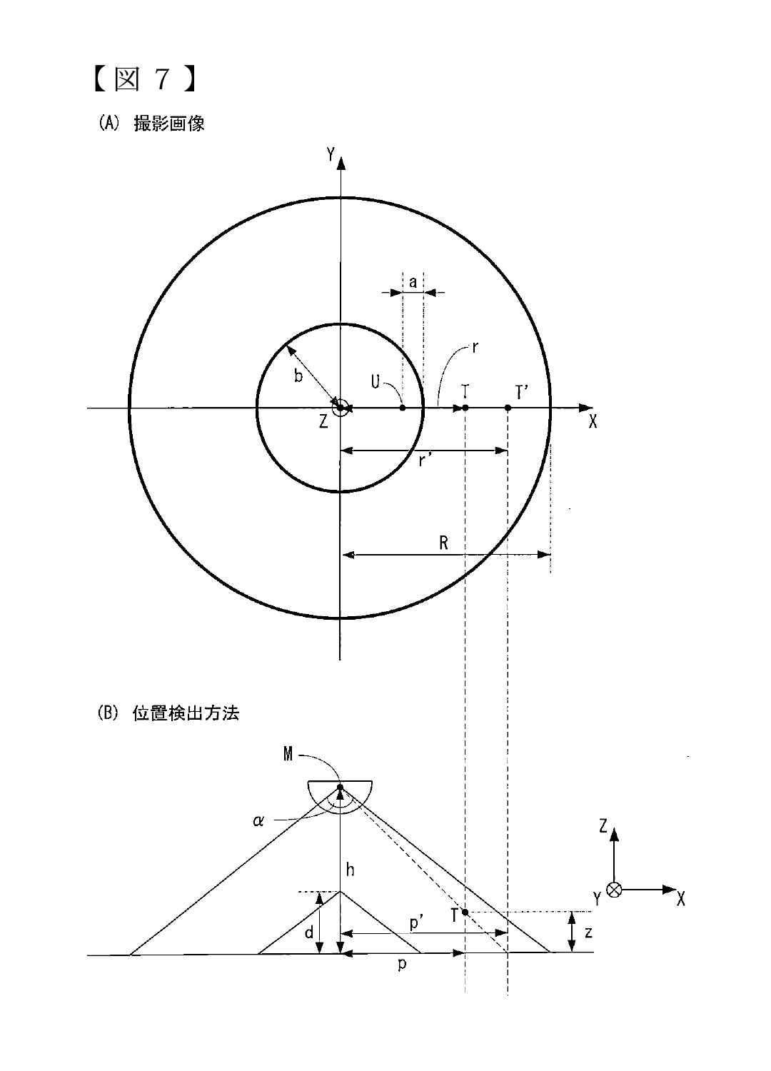
[Drawing 7]Fig.7 (A) is other examples of the taken image of an imaging device, and Fig.7 (B) is an explanatory view for describing the method of computing the position of the finger when not having touched.
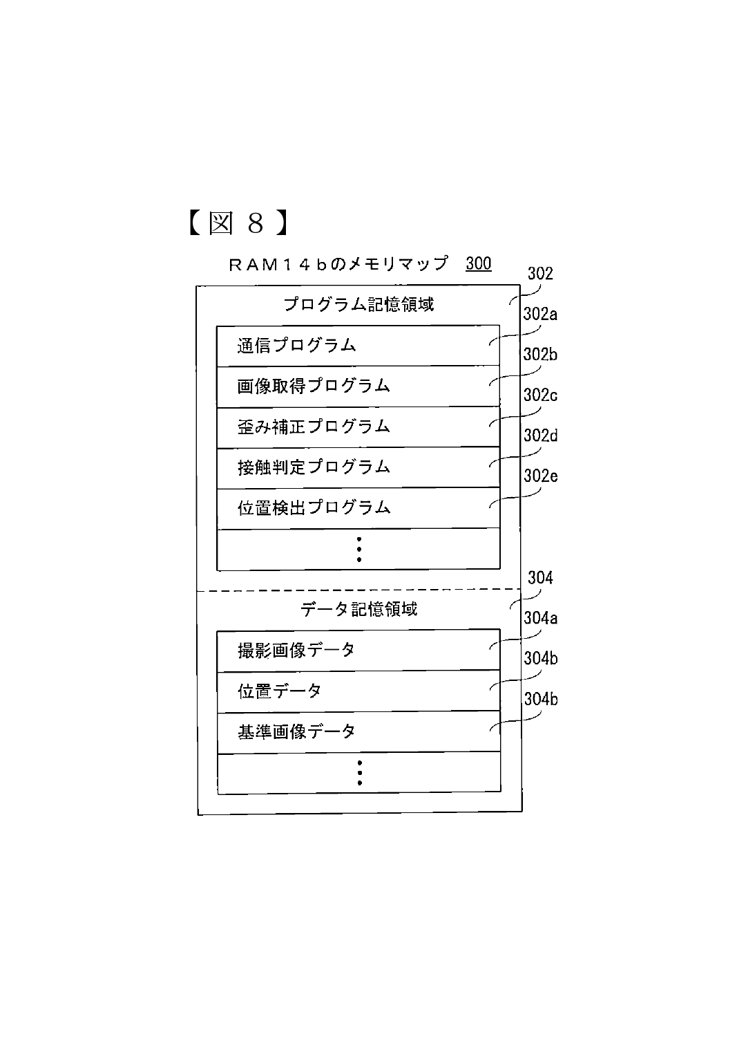
[Drawing 8]Fig.8 is an illustration figure showing an example of the memory map of RAM built in the computer shown in Fig.1.
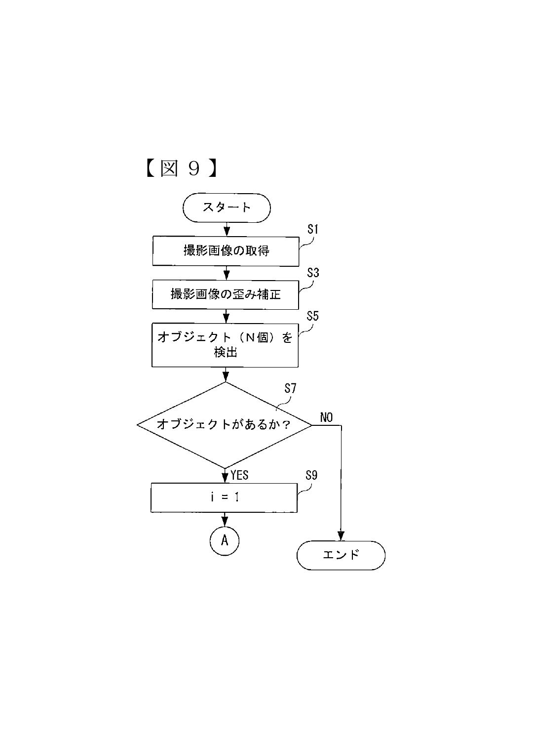
[Drawing 9]Fig.9 is a flow chart showing a part of position detection process of CPU built in the computer shown in Fig.1.
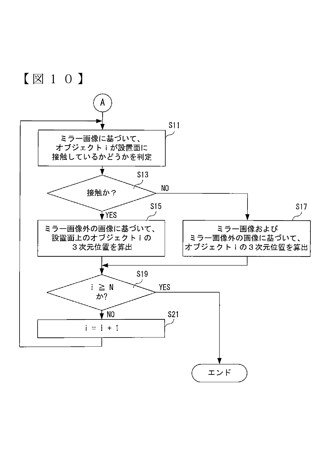
[Drawing 10]Fig.10 is a part of other position detection processes of CPU built in the computer shown in Fig.1, and is flow charts which follow Fig.9.
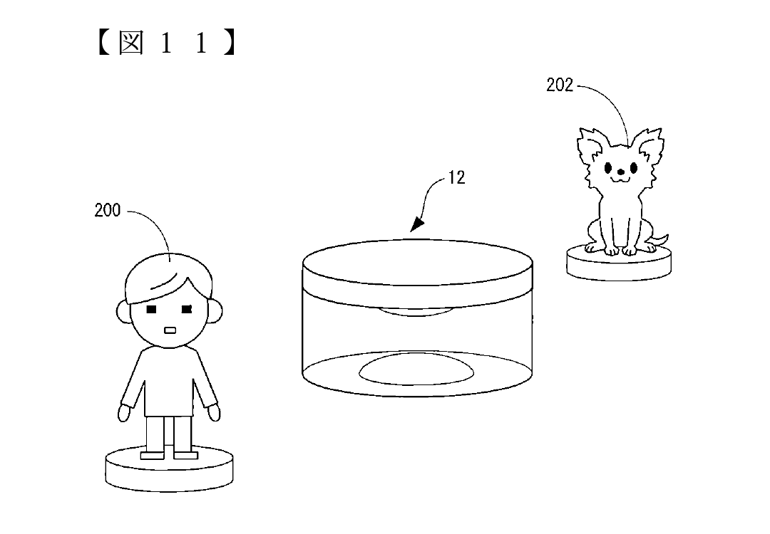
[Drawing 11]Fig.11 is an illustration figure showing the example of the detecting position of other objects which used the information processing system of the working example.
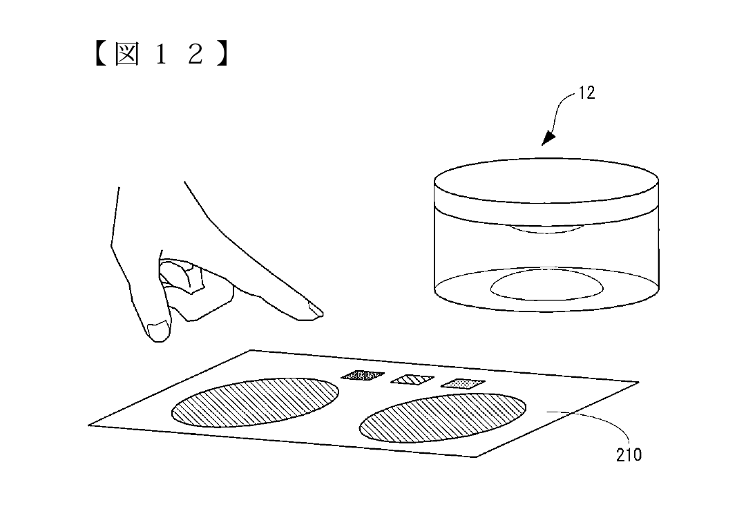
[Drawing 12]Fig.12 is an illustration figure showing an example of the user interface which used the information processing system of the working example.
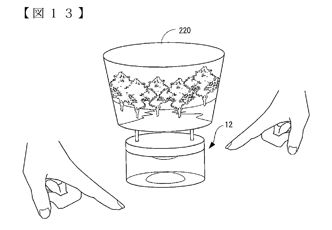
[Drawing 13]Fig.13 is an illustration figure showing the example which provided the display for exclusive use on the imaging device of an working example.
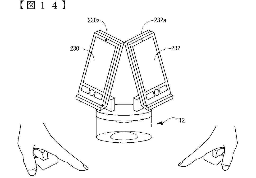
[Drawing 14]C Fig.14 is a shown illustration figure about the example which provided the display removably on the imaging device of an working example.
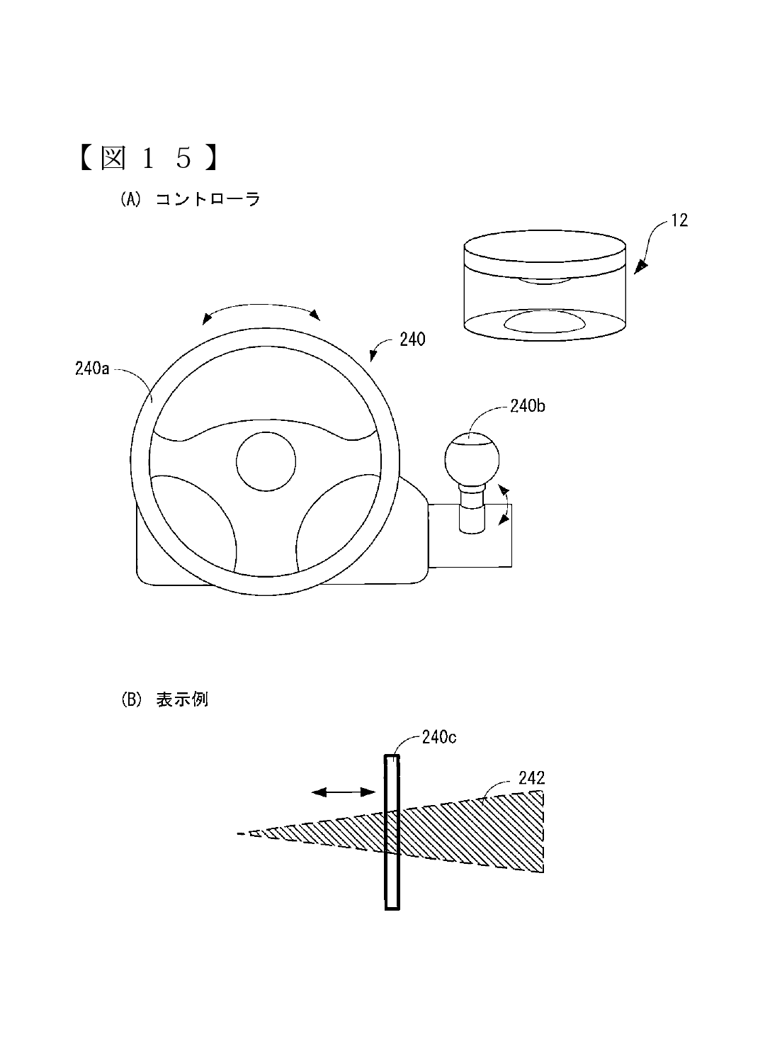
[Drawing 15]Fig.15 (A) is an illustration figure showing the example which constitutes a controller using the operating part of an information processing system and resin, and Fig.15 (B) is an illustration figure showing the display example of the display window provided by the operating part.
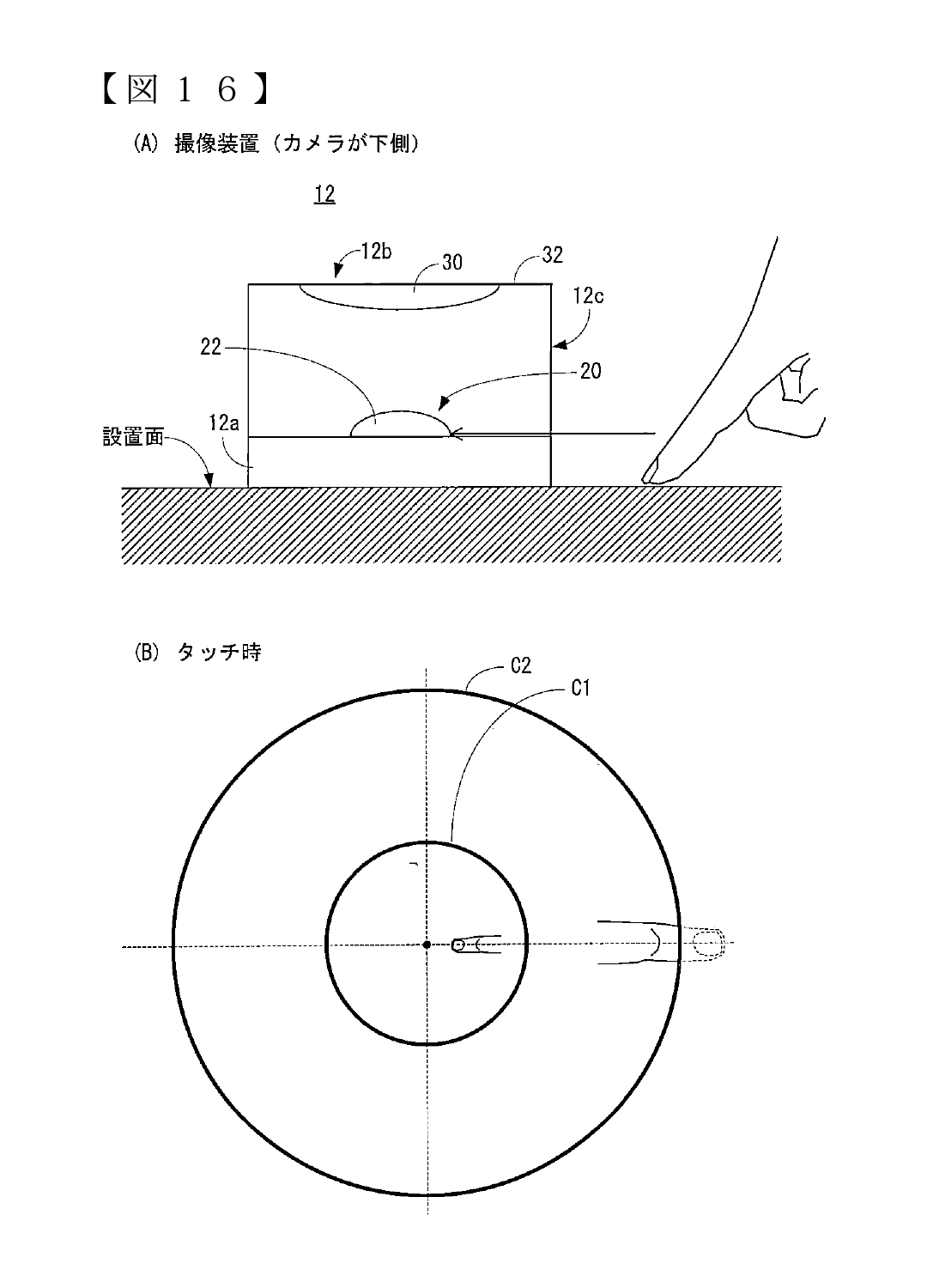
[Drawing 16]Fig.16 (A) is an illustration figure showing the state where the imaging device was installed for upside down at the setting surface with the case of the working example, and Fig.16 (B) is an illustration figure showing an example of the taken image photoed in the state which showed in Fig.16 (A).
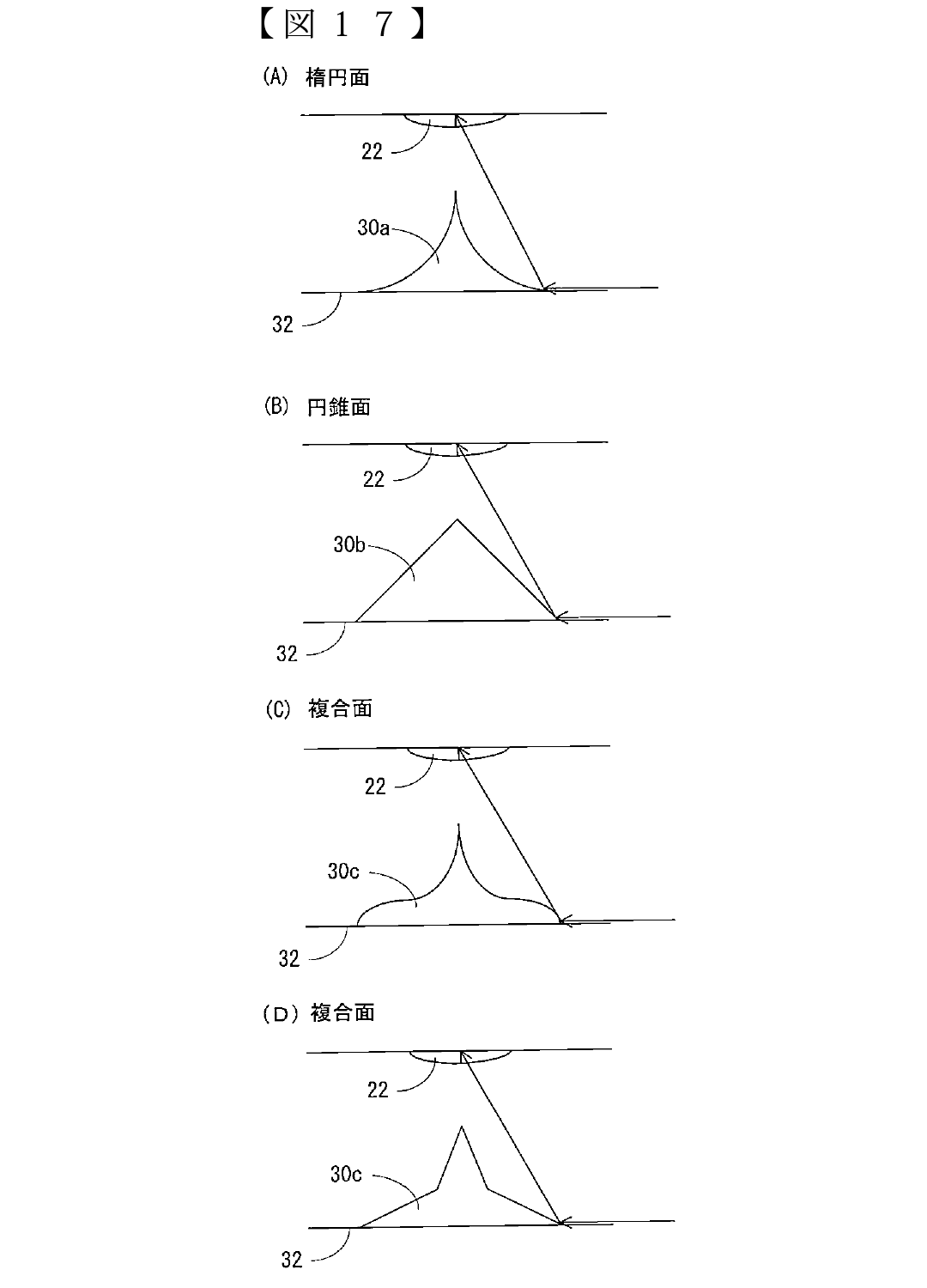
[Drawing 17]Fig.17 (A) is an illustration figure showing the curved surface mirror of an ellipsoid, Fig.17 (B) is an illustration figure showing the curved surface mirror of a conic surface, and Fig.17 (C) is an illustration figure showing an example of the curved surface mirror of a compound surface, and Fig.17 (D) is an illustration figure showing other examples of the curved surface mirror of a compound surface.
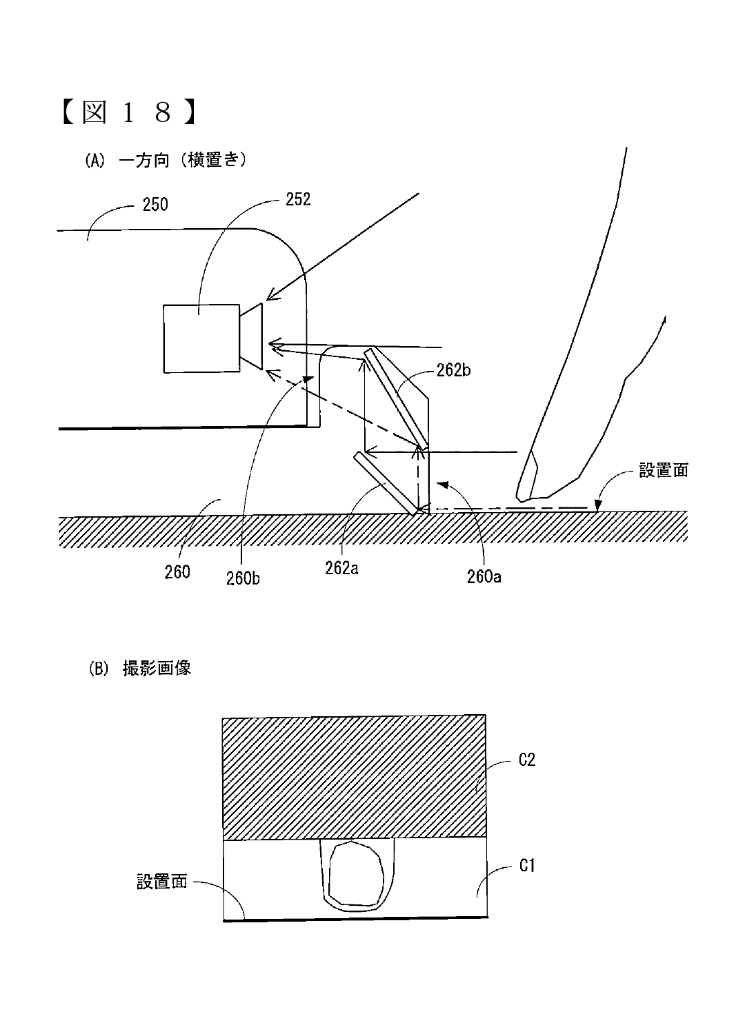
[Drawing 18]Fig.18 (A) is an illustration figure showing the schematic configuration diagram of other examples of an information processing system,
Fig.18 (B) is an illustration figure showing an example of the taken image of the camera shown in Fig.18 (A).
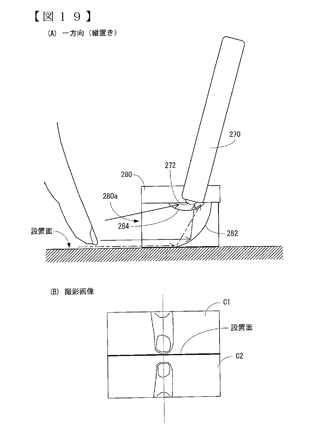
[Drawing 19]Fig.19 (A) is an illustration figure showing the schematic configuration diagram of the example of others of an information processing system, and Fig.19 (B) is an illustration figure showing an example of the taken image of the camera shown in Fig.19 (A).
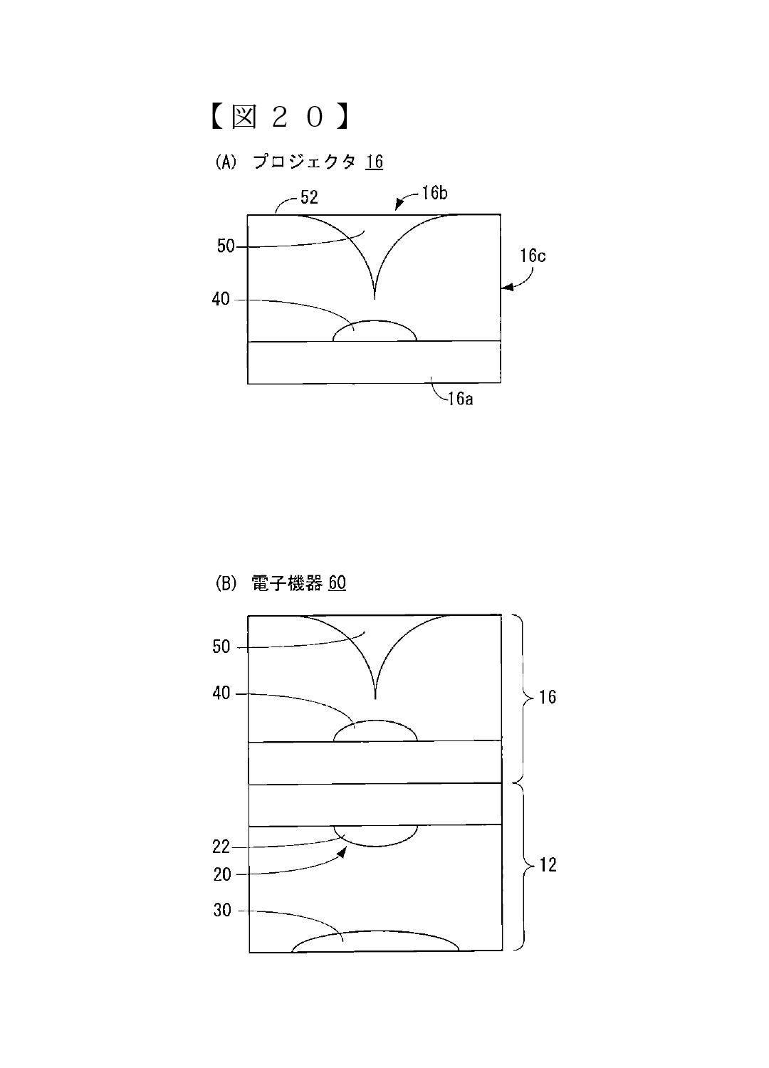
[Drawing 20]Fig.20 (A) is an illustration figure showing an example of the appearance composition of a projector device, and Fig.20 (B) is an illustration figure showing an example of the appearance calibration of the electronic device which constituted the imaging device and the projector device integrally.
Descriptions - Excerpts
[0053] The 24th invention is a projector device which opposes to a light source and a light source, is arranged, and is provided with the mirror which reflects the light from a light source in the circumference.
[0054] According to the 24th invention, an image can be projected on the surface which intersects the surface in which the projector device was installed, and the surface concerned.
[0062] With reference to Fig.1, including the imaging device 12 and the computer 14, as for the information processing system 10 which is one working example of this invention, theimaging device 12 and the computer 14 are connected so that a wireless communication is possible. However, the imaging device 12 and the computer 14 may be connected by the cable so that communication is possible.
[0064] The camera unit 12a is circularly formed by top surface view, and contains the camera 20 using an image sensor like CCD or CMOS. The camera 20 is electrically connected with the electronic component which performs imaging processing and communications processing so that it may mention below, and such an electronic component etc. are stored in the housing of the camera unit 12a. The mirror part 12b is circularly formed by top surface view, and contains the fixing member 32 which fixes the curved surface mirror 30 and the curved surface mirror 30 concerned. The curved surface mirror 30 is circularly formed by top surface view, opposes to the camera 20 and is provided. The curved surface mirror 30 has a convex (this working example hyperboloid) projected to the camera 20 side. The fixing member 12c is cylindrical shape, and is formed with transparent resin or glass. The height (length) of the fixing member 12c is determined by predetermined length. When the imaging device 12 is placed on a predetermined surface so that it may mention below, the positional relationship of the camera 20 and the curved surface mirror 30 and the form (form of a surface) of the curved surface mirror 30 are determined so that the light which he proceeds along the predetermined surface concerned in a beam direction parallel to the predetermined surface concerned may be reflected at the end of the curved surface mirror 30. Therefore, the height of the fixing member 12c is determined so that it may become such positional relationship. However, the light reflected by the curved surface mirror 30 enters into an image sensor via the wide-angle lens 22 of the camera 20.
[0065] Fig.3 is a block diagram showing the electric composition of the camera unit 12a. The camera unit 12a is connected to ROM104, RAM106, and the communication module 108 while CPU100 is connected to the camera 20 mentioned above via the internal bus 102 including CPU100.
[0068] For example, the imaging device 12 is placed thru/or installed on a desk and a predetermined surface like a wall surface (a white sheet etc. are included), and the computer 14 computes the position of the object (object) which exists in the circumference of the imaging device 12 (detection). In this working example, a user's finger judges whether it is in contact with the predetermined surface (touch), and has computed the position (three-dimensional position in real space) of the finger concerned.
[0069]
[0123] The information processing system 10 can be used as a user interface (UI) by using the paper 210 as shown in Fig.12. For example, the button pattern equivalent to a manual operation button is drawn by the paper 210. Direction of the imaging device 12 and the paper 210 and a position are set as the relative direction and position which were determined preliminarily. As the above-mentioned working example showed, the computer 14 judges whether the user's finger contacted the setting surface of the imaging device 12. If it judges having contacted, the computer 14 will compute the position of the finger which touches and will judge the touched button pattern on the paper 210. And the computer 14 outputs to application the command set as the button pattern (manual operation button) it was judged to be that a user's finger touched.
[0125] As shown in Fig.13, the display 220 for exclusive use can be provided and touch operation can also be performed using the display 220 concerned. However, two different users' hand is illustrated in Fig.13. For example, the display 220 is connected to the computer 14 and a display is controlled by the display controller built in the computer 14 under the instruction of CPU14a. The display 220 of the example shown in Fig.13 is formed in cylindrical shape, and is installed on the imaging device 12. For example, it can be used by one user or a plurality of users, without dividing the display area of the display 220. The display area of the display 220 can be divided according to the number of users, and it can also be used individually.
[0126] It may be made to provide a display (230a, 232a) removably to the imaging device 12, as shown in Fig.14. However, two different users' hand is illustrated in Fig.14. For example, in the example shown in Fig.14, a smart phone and an electronic device (henceforth a "personal digital assistant") (230, 232) of an integral type [ display / (230a, 232a) ] like a tablet PC are installed on the imaging device 12. The computer 14 and communication are possible for a personal digital assistant (230, 232), it performs processing of application according to the manipulation data transmitted from the computer 14, and displays an executed result on a display (230a, 232a). That is, the information processing system 10 which comprises the imaging device 12 and the computer 14 is used as a common pointing device in this case, and the computer 14 detects the touch operation for every user, The manipulation data according to the detected touch operation is transmitted to a corresponding personal digital assistant (input). That is, in this case, the information processing system 10 can be used as an input device of a personal digital assistant (230, 232), and while looking at the whole screen of a personal digital assistant (230, 232), it can input.
[0128] As shown in Fig.15 (A), the information processing system 10 can also be used as a controller by using the operating part 240 of the resin which does not have electric composition. For example, the handle 240a and the lever 240b are provided by the operating part 240, and the display window 240c as shown in Fig.15 (B) is provided by the back side of the operating part 240 shown in Fig.15 (A) at it. As shown in Fig.15 (B), the marker 242 who is interlocked with operation of the handle 240a and moves to right and left is in the housing of the operating part 240, and it is arranged in the position where the display window 240c is provided. Specifically, if a user turns the wheel 240a to the right, in Fig.15 (B), the marker 242 will be moved to the right. Therefore, the length of the marker 242 seen through the display window 240c becomes short. On the other hand, if a user turns the wheel 240a to the left, in Fig.15 (B), the marker 242 will be moved to the left. Therefore, the length of the marker 242 seen through the display window 240c becomes long. The computer 14 can know how much the wheel 240a is turned by which right and left (angle of rotation) among the taken images photoed with the imaging device 12 according to the length of the longitudinal direction of the marker 242 seen through the display window 240c to the length of the longitudinal direction of the display window 240.
[0129]
Source: Search "2016-45173)" (under Publication of patent application) here.